Where do we stand and how did we get here.
When i first started FSWizard project one year ago in December 2011. I felt the need to upgrade my knowledge and skill-set regarding speeds, feeds and best cutting conditions.
Other calculators available at that time simply did not cut it for me.
One of them did not account for such important parameters as tool length.
The other did not care about such crucial tool geometry features like helix angle, shank diameter, lead angle and so on.
As a result i have endeavoured on a mission to build the best calculator that would accurately predict cutting forces, cutter deflection and suggest best cutting modes using all available tool data for multitude of combinations of work-piece/tool materials, coatings and tool types.
It has been a year of research, building cutter and material models, applying REAL MACHINING experience.
All results were tested in REAL PRODUCTION environment.
Today thanks to FSWizard, machines i work on produce 200%-300% more parts per day than 1 year ago.
It has been one year since i have started.
And i believe i have achieved my original goal.
Today The FREE FSWizard gives far better results than many expensive solutions available on the market.
FSWizard:Standalone is the only available program that will warn you if cutter will be reaching its breaking point.
In fact we see paying users of other programs asking their developers for features that have been long implemented in FSWizard.
And we see those developers finally moving out of their comfort zone and trying to improve their program's functionality.
Where do we go from here?
What does the future hold for this project?
No one really knows.
Unlike others who can talk the speed/feed game, I am not into marketing.
I don't do a particularly good job of persuading people that my product is the best thing that happened to the CNC world.
All i have is 2 hours of free time on my hands after work and a ton or real-world machining experience not many in the software business can brag about.
All that remains to say here is
I am not using words "product" ,"consumers" and "business" just by accident.
Next release version of FSWizard:Standalone 0.015 PRO will be a commercial product.
It will be sold as a 1 year subscription.
I am not yet sure about the pricing.
But i know that i will make it subscription-based and the price will be very affordable.
This is the only way to move forward on this.
If you have any comments or thoughts, i would love to hear them out.

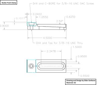
 Drawing