I personally use HSMAdvisor at work every day and trust its results 100%
I have to say my program now knows about machining more than i do. I certainly can not remember cutting speeds and feeds, reduction factors, depth of cut and a ton of other information for every material I have ever cut.
Now add to that the various possible combinations of tool/material/coating and it becomes a no brainier, that a good speed and feed calculator like HSMAdvisor saves a ton of time and money by improving your tool life and productivity.
It is not only good for HSM (High Speed Machining) but also for general machining, drilling tapping, you name it.
The algorithms it employs are far superior to what other calculators are using. Take for example the real-time depth of cut/deflection optimization, that other calculators do in a separate window and take a few seconds to complete.
Here is a quick video lesson where i show the steps involved in creating a simple contouring toolpath in MasterCam x9:
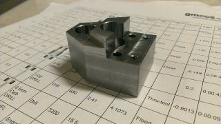
And here is the video of machining the actual part: