Subscribe to Blog
Email Address
 
All related to speeds and feeds on different materials
Pages:(2) [1] 2

Avid CNC Benchtop Pro: HSM and High Feed Milling

March 15, 2020, 3:36 pm by Eldar Gerfanov (Admin)

On the heels of the previous post.

YouTuber Breaking Taps has just published another of his interesting videos:

In it he is testing various High-Speed Machining techniques on his benchtop CNC router.

Also it is mentioned that HSMAdvisor does not seem to like those small high-feed cutters: at some point some calculated values become negative.

This is a legitimate criticism and it actually happens because default cutting depth of 0.024" becomes too large for the 0.24" Lakeshore high feed and mill and an actual Flute length of 0.015" must be entered in order to get proper values:


With actual 0.015" flute length entered the recommended speed and feed values are now in the safe end of the ballpark suggested by the manufacturer.

Task added to the issue tracker!

A Total Guide into Plunging and Ramping

April 4, 2017, 7:33 pm by Eldar Gerfanov (Admin)

Before we start milling away our stock we first need to get down to the required depth.

This is not a problem with external features when we can plunge outside.

When machining closed pockets, however, we need to find a way to get down to the machining depth first.

As usual there are several ways to get the job done. The plunging methods listed here are not ordered by their preference.

For various machining operations on different materials some may be more preferable than others.

Straight Plunging into a larger Pre-Drilled hole

This is one the best ones in my opinion.
Very few machining modes can compete in effectiveness with drilling and this method will get you the best combined tool life on most materials and (in case of many deep pockets) the least machining time, even when tool change time is factored in.

When using a pre-drilled hole technique, though, you should keep in mind that holes tend to collect chips and I would recommend machinists to make sure the holes are clear before plunging in. This can easily be done with an air blast or a through-spindle coolant.

Most CAM software allow you to specify a drilling operation for a pilot hole. With MasterCAM's Dynamic Toolpaths, for example, I would normally create a hole geometry where I want the pilot to be and use it as "Air Region" when chaining my ToolPath, this would ensure my milling tool uses the hole region for plunging without the need for ramping.

Straight plunging into solid stock

On aluminums, soft non-ferrous and non-metals this method gives best productivity and tool life. It also requires just one cutting tool for both plunging and milling.

A few conditions have to be met for this method to be successful.
First of all your end mill is supposed to be designed for straight plunging. In other words it needs to be center-cutting.

Ideally the depth of your plunge should not exceed one diameter of the end mill.

When calculating spindle speed, I recommend using 70% of normal slotting cutting speed for this material and the feedrate should be divided by the number the End Mill's flutes.

HSMAdvisor by default suggests plunging Speed and Feed according to these guidelines.

To avoid having chips wrap around your tool you can use pecking or chip-break motion to break the chips. In such a case 1/4 to 1/8 diameter pecks usually help.

Straight plunging into a Pilot Hole that is smaller than the End Mill

When milling plunging into steels and other tougher materials, or when chip welding becomes an issue it is possible to straight-plunge into a smaller pre-drilled hole.

Yes, this method requires a separate drilling tool to make the pilot hole, but, unlike the previous one, it will let you use non-center-cutting tools and improve the chip evacuation.

Here is a neat trick to avoid chips from wrapping around your End Mill: shift your Pilot Hole in such a way, that the drilled hole is tangent to the circumference of the end mill:

This method plays well when you have to make a counter-bore on a hole, that you had to make anyway.

Alternatively You can also use pecking motion to break the chips.

On most mild materials this method gives good tool life and productivity.

Helical plunging into a Pilot Hole smaller than the End Mill

Not always we can find a drill larger than the diameter of the End Mill.

In this case we can drill a smaller hole and helical-plunge into it at more aggressive feed and speed rates than we otherwise would ramping into the solid stock.

HSMAdvisor considers the size of the pilot hole when calculating plunging speeds and feeds. You can read more in depth over about it over here: Circular Interpolation / Ramping Calculator

This method works for tougher materials when it is impossible to to straight-plunge, or when chip-welding is an issue.

Helical plunging into solid stock

Helical Ramping is a lot like straight line ramping, it also requires slower cutting speeds and feeds, but unlike linear ramping it requires circular motion of the cutter and can be subject to pocket geometry constraints.

It is suggested to use 0.9 to .95 of the cutter diameter for the diameter of the helical path (resulting hole almost 2x dia of the end mill) and sometimes it is hard to fit such a large hole in a pocket.

This method is my least favorite but because it is so easy to use, I often default to this one, as it requires the least amount of thought.

Ramping is also the only method that will work when milling hardened steels. Unless you have a large carbide drill to put a pilot hole, of course.

Linear ramping into solid stock

Any Full-width ramping method requires much slower cutting speeds and feeds than normal milling would.

Since in this scenario the End Mill effectively has 360 degree engagement with the work-piece, cutting speed needs to be reduced in order to not damage the cutting edges.

By the way HSMAdvisor considers not only the plunging mode when suggesting speeds and feeds, but also ramping angle. It outputs separate plunging parameters on the "Speeds and Feeds" panel.

The pro of this method is better chip clearance when making long linear ramping motion and the con of this method is that often long linear ramping moves are not possible due to pocket geometry constraints.

Speeds and Feeds

As previously mentioned, almost any case of plunging requires cutting speeds and feeds different than those for regular milling.

For non-HSMAdvisor aided programming i suggest using 50-80% on normal cutting speed and feed adjusted according to the following table:

Ramp chipload adjustment for 4 flute Center cutting end mills:

  • 0-2.5deg=100% of normal feedrate
  • 2.5-5deg=75% of normal feedrate
  • 5-15deg=50% of normal feedrate
  • 15-30deg=25% of normal feedrate
  • 30-45deg=5% of normal feedrate

When HSMAdvisor is used to calculate plunging speeds and feeds, it will automatically adjust speeds and feeds according to the entered conditions.

In this help article I explain in detail for to use HSMAdvisor's many supported plunging modes:

http://hsmadvisor.com/?page=help&shell_id=241&article_id=4781_circular-interpolation-ramping-calculator

Combating Chatter: 4 reasons to NOT reduce your feedrate

April 30, 2016, 6:58 pm by Eldar Gerfanov (Admin)
HarndenedLayer.png

We all have heard hundreds of times that when chatter is happening during machining, we should reduce our feed rate. The same advice we also hear for compensating for extra-long tools and unstable setups.

Let me explain why I think this is mostly incorrect.

Let’s list  the effects of reducing the feed rate:

  1. Reduces tool life.
  2. Reduces productivity.
  3. Increases deflection.
  4. Causes chatter.

Let me explain from my own experience and research I have made each of these points and a simple way to avoid chatter's adverse effects.

Reduction in chip-load reduces tool life.

This may seem counter-intuitive, but the tool gets the best cutting edge life only within a narrow window of chip-load range and cutting speed.

Reduce your chip load below a certain value, and you will be hurting your tool life a great deal.
Yes, your tool may run longer, but it will do a lot less work before it gets dull!

Reduction in productivity

This point follows right out of the previous one. Not only your tool now moves slower, thus reducing the material removal rate, but you also have to replace it more often. That adds extra setup time cost too.

Increase in deflection

Cutting action is a fine balance between a cutting edge plowing through the material, rubbing and shearing it. We want to do as much shearing as possible and less plowing, and ideally, no rubbing.

I recently did a test cutting 6061 Aluminum plate with a 1” long .25” dia Grooving tool and measuring its deflection at different chip-loads:

You can clearly see how below 0.0005” chip load (X-axis) bar deflection is double of what it should be if you were to follow the light-blue trend line. Here, we are getting 0.001” deflection!

Then once we increase the chip load to 0.001”, the tool is not rubbing anymore, and we get 0.0015” deflection - not double, but only 150% of deflection increase for 200% increase in chip-load.

The line continues steadily until we hit 0.003” chip load, and then it almost takes a dip!

Between 0.003” and 0.004” chip load, we get just 0.001” increase in deflection instead of projected 0.002”.

This means that the perfect chip load for the boring bar I was using is between .003” and .004” because right after the sweet spot, at .005” chip load, we get a sudden spike in deflection up to 0.010.”

As cutting edge (ideally) shears off a slice of the material, it hardens the work-piece right underneath. This layer of material will be sheared off by the next (or the same in case of a single flute) cutting edge.

If our chip-load is too low, we will be cutting right through the work-hardened surface, thus decreasing tool life (see point one) and actually increasing the cutting pressure.

Also, the cutting edge is not ideally sharp. It has an edge radius, half of which will be pushing the material up and the other one - down. So you will be having a lot of plowing and rubbing action too.

Because one image is better than a thousand words:

The red surface on the picture is the work-hardened layer. The green one - workpiece with the regular hardness. We want the cutting edge to shear off underneath the hardened layer.

Induces Chatter

In many cases, a lower feed rate may actually be the reason for chatter in the first place.

Have you ever heard an experienced machinist tell somebody to “load-up that tool” to prevent chatter?
You are most likely such a machinist, and you have noticed that increasing the feed rate may actually reduce chatter.

Why does chatter occur?
It is a combination of the above mentioned factors such as an increase in cutting pressure causing deflection and unstable cutting conditions.

The tool deflected by the cutting pressure tries to return to its original shape, and lack of chip load allows it to do so unobstructedly. The tool pretty much vibrates freely. When that happens thousands of times per minute, you get your tool singing.

When you increase the feed rate, you may actually create more stable cutting conditions and eliminate chatter.

So what should I do if I am already getting chatter?

First of all, make sure you are using proper speeds and feeds, to begin with.
Call your tool vendor to get proper numbers for your particular case, or try our HSMAdvisor- Advanced Speed and Feed Calculator.

HSMAdvisor will suggest you perfect starting speeds and feeds, and also it will suggest you proper Depth and Width of cut for your particular workpiece material and tool configuration.

If you used HSMAdvisor, chances are you are not going to get any chatter at all!

If you did not and want to go with your tool vendor' numbers - fine - try their speeds and feeds on your machine.

Did it help? If not, here is the simple solution:

Reduce the Depth of Cut!

While a reduction in chip-load leads to more rubbing, it does not reduce the cutting pressure in the same way the DOC reduction does.

For example. We might only need to reduce the DOC (and thus cutting pressure) by 20%, and the chatter will go away. The same effect would require us to reduce the feed by 50% or so if we are lucky. If we are not lucky, even further reduction in feed rate will not eliminate the chatter.

So in conclusion:

Whenever you are having chatter issues, get proper Speeds and Feeds and reduce that DOC!

Best Regards

Perfect Ballnose Engraving Speeds and Feeds in Production Environment

December 6, 2015, 12:38 am by Eldar Gerfanov (Admin)
ballnoses_stepover.png

I regularly follow practicalmachinist.com forums.
Especially the cnc machining section of it.

I notice when CNC Speeds and Feeds questions come up people often suggest my HSMAdvisor Machinist calculator.
A referral by a satisfied customer is the best referral in my opinion. Thank you to everyone doing this great favor to me and my prospective users!

Other times users of HSMAdvisor question speeds and feeds it generates and instead of going to me, they ask on forums.
Which is always fine, because extremely often "wrong" results mean something wrong in users expectations or the data he feeds the calculator

In the process of discussion it usually turns out that the calculation results were correct, but because user decided to use a depth of cut or tool length, larger than he should have, HSMAdvisor compensates and gives a very conservative feed rate.

Just like in this forum post over here: Engraving with a 1/32 ball mill machinist wanted to use a 1/32" ballnose endmill to engrave 304 Stainless Steel at 0.010" depth of cut.

Quote:
Material is 304 laser cut, machine is a Haas VF-6SS with a 12k spindle. Obviously spinning at 12k, but what would everyone's feed be at .01" deep? HSMAdvisor always seems to me to be very low on these numbers (1.41 IPM? Yes this is with chip thinning turned on). Tool has a 1/4" shank and a real short flute length, solid carbide AlTiN coated.

Naturally HSMAdvisor was not too happy and suggested a very low feedate for such an operation.
Proper depth of cut would be about 0.002" for such a small tool and it would yield a much faster cutting rate.

Eventually, though, machinists who have run similar jobs pointed out that the Depth of Cut was excessive for such a tool/material combination and suggested both larger tool and shallower depth of cut.

Quote:
Why .010 deep with a 1/32? Why not .005 with a 1/16 and triple your feedrate?

Quote:
That sounds deep to me as well. I end up going only a few thou deep to get a pretty decent width line. Sneak up on it, and either ramp in or slow down the plunge like Haazart said.

Eventually the original poster changed to a 1/16" ballnose and 0.005" depth of cut.

Quote:
I'm going to change it to .005" with a 1/16" cutter. This is going straight on the subplate, so if it varies I'm going to blame Chick Workholding. Which I wouldn't mind doing anyway

Edit: got the part indicated with a tenths test indicator (I have a VERY short flat to work with) within two tenths end to end, and checked the flatness of the part. Around the area to be engraved it's all within five tenths. Should work okay.
 

Quote:
Wish I could take a photo to show, but it came out awesome. 12k, 10.7 IPM, .005" deep.
 

What do you know!
That's exactly what HSMAdvisor suggests for a 1/16 ballnose and it apparently worked out awesome!

Thank you, Atomkinder for the follow up on the results of your machining!

Key factors Determining Success of High Speed Machining (HSM)

September 12, 2015, 7:29 pm by Eldar Gerfanov (Admin)

As a developer of a very successful line of speed and feed calculators I sometimes get questions like : "I calculated speeds and feeds for a conventional toolpath. Got 5.5 cubic inches MRR(Material Removal Rate). And then I calculated S&F for the same endmill with HSM parameters turned on and got almost the same amount of  MRR! What is even the point in using HSM parameters?" -they ask.

I would like to clear some things up for my friends.
In this article I will explain exactly WHY HSM machining is better and HOW to achieve better productivity and tool life.

For starters here are the main features of a HSM-capable cutter:

As usual there are several components of HSM that need to be present in order for it to work to its fullest. These are:

a) Machine
b) Tool
c) Workpiece geometry
d) Workpiece material

I intentionally did not number these as each one of those is equally important.

a) Machine. You need to use a very rigid machine that is designed by the manufacturer to operate at high feed rates and cutting forces. If your machine is not up to the task, however, it does not mean that HSM machining will fail, but simply that you may not be able to utilize the spindle time to its fullest. There still are ways to successfully use HSM on older machines. And we will talk about it later.

b) Tool. Your tool should be designed for HSM. Tools, that are capable of performing conventional operations sure CAN, but are not the best at it by a wide margin.
Tools designed for HSM have thicker core to sustain high cutting forces. They have a lot more flutes stuffed into the same tip diameter than their conventional brothers. IE. a 1/2" HSM Endmill can have 7-10 flutes versus 4-5 for a standard endmill.
A cutter with so many flutes on such a small diameter simply can not effectively do any conventional milling at all.

Thus any attempt to compare "apples to apples" fails miserably. You just have to start comparing apples to oranges.

HSM cutters often have corner radius to prevent chipping. And some models even have a geometry of a feed mill on the end to allow for high speed ramping (where with of cut will be equal to the diameter of the cutter) into the material.

c) Workpiece geometry.
HSM machining with an end mills requires large depths of cut. Simple as that.
You part needs to have deep cavities and tall walls. At low radial engagement HSM cutters can take full flute depths of cut with almost no additional tool deflection. Your depths of cut should be more than x2 of the tip diameter. And they can be as large as x4 of the tip dia. without the need to compensate for that.

d) Workpiece Material.
Should be hard or tough material. Such as Stainless steel, titanium, tool steel, hardened steels. Maybe Mild steel. But not aluminum. aluminum is easy enough to machine the conventional way. With fluffy soft materials it may simply be impossible to compensate the lost air time with higher feed rate.

Lets compare performance of two 1/2" endmills in machining a 1.5" deep pocket in D2 Tool steel.

One is 1/2" 4 Flute TiAlN coated High Performance Endmill.
Because we will machine a 1.5" deep pocket the conventional way.
Our DOC (Depth of Cut) will be just 0.226"
MRR for this operation will be: 2.49 in^3:

Another tool is 1/2" 6 Flute TiAlN coated High Performance Endmill designed for HSM machining
Our DOC (Depth of Cut) will be 1.5" with 0.05" radial stepover
MRR for this operation will be: 5.96 in^3

Almost 6 cubic inches of metal removal versus 2.49 is more than twice the productivity!
And that was calculated with very conservative settings.

In addition to that You can also see that estimated Tool Life has increased to 149%.

This is basically it.

Let me know if something else needs more clarification and i will explain this article.

You may also like to learn about:

A new Help article on HSM

September 2, 2015, 10:23 pm by Eldar Gerfanov (Admin)

I often get email questions asking for clarification on merits of use of HSM And Chip Thinning check boxes when calculating speeds and feeds with HSMAdvisor and FSWizard calculators.

In this new help article will try to explain just what HSM means and in which situation you should use it:

http://hsmadvisor.com/index.php?page=help&shell_id=241&article_id=4574

Hopefully this will fill in the gaps and help our users to get more comfortable with our software.

Regards!

An interesting conversation

July 12, 2014, 10:32 pm by Eldar Gerfanov (Admin)

A few days ago one of FSwizard:PRo users questioned me over how FSwizard works.

The way SFM calculates seemed off to him.

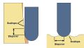
As a result i made a quick sketch for him, that i thought i would share here.

Omar was asking me how come SFM seemed wrong for a 1" dia ball-nose cutter when making shallow depth cuts.

The sketch above shows exactly why.

On the left part we see a cutter engaged into the material to the depth equal to its corner radius.
At that depth the maximum effective diameter is achieved. So an old good RPM=4xSFM/Dia formula would apply.

But at shallower depths, effective diameter of the cutter is reduced.

At 0.1" depth of cut, effective diameter would only be around 0.6"

In fact it goes to zero at the very centre. So a higher RPM will be required to achieve the recommended cutting speed.

In the same thread i also explained how DOC/WOC balancing works.

So if you are interested - read on.

Here is the thread http://zero-divide.net/index.php?page=forums&shell_id=170&article_id=4590


A few tips on surface milling with ballnose endmills.

November 18, 2013, 1:13 am by Eldar Gerfanov (Admin)

Since surface milling is more than half of what i do for a living, I decided to share some of my tips on that topic.

Generally you want to create a continuous toolpath that does not change directions too often.

Changing directions slows the machine down and reduction in feedrate affects deflection of the cutter. Different deflection means you get gouge marks on your surfaces.

When you have a long narrow piece its better to go along the long side to save on time and machine wear.
Also going along the longest side reduces the number of direction changes you will have to make

When milling cavities you need to first rough, then semi-finish then finish.

Leave 15 thou after roughing, 3 thou after semi-finishing and finish to zero. All with progressively smaller tools.
5 thou stepover will give you very good finish on most ball mills
3-5 thou chiploads are very common for surface finishing.

Ball mill will always give bad finish on shallow areas- the center is not cutting, but dragging around.
Also straight portion of the flute acts as a wiper and reduces scallop that the ball portion creates.

This is why going from top to bottom is safer and yields better surface finish.

The closer the wall taper angle to the taper of the flutes the better finish you will get.


There is another reason for always trying to go from top to bottom.

When taking material top to bottom you engage stock closer to the tip of the tool.

It makes cut more stable. It is more safe because you are less likely to bury the tool in stock unexpectedly.
Do not go from climb milling to conventional UNLESS you need to save some rapid time.
Pick up only climb milling and you are good to go.
Changing from climb to conventional will cause tool to deflect away from the work on climb and into the work during conventional pass. You will see zebra marks all over your surfaces.


Ways in which High Speed Machining (HSM ) works

October 12, 2013, 11:32 am by Eldar Gerfanov (Admin)

Lately there have been a lot of really interesting HSM topics on PracticalMachinist forums.

In one of them a guy who owns his own resharpening business posted a video of his endmill milling a block of D2 hardened to over 60 RC.
The forum topic is located here First try on D2 62Rc(video)

Here is his post so you know what we are talking about:

Quote:
In an effort to perfect our speeds and feeds while hardmilling, this is the first try. Its not right yet, but far from a failure. I apologize for the language at the end, but I do not edit my videos. The endmill was a reground garr VRX at .353 diameter. Parameters were 750 sfm, .018 radial, .300 axial and .004 ipt.
The next run will be at 650 sfm, .006 ipt using a mist sprayer. Also, any small areas will be blocked off to be ran at lower speeds to allow cooling time for the cutter. Just a note for anyone using a Mag Fadal, The E-stop button is not quick enough, use feed hold. The endmill was badly worn on the corners, but not broken, and will be resharpened and used again.

In the ensuing discussion i posted my own take on how and why HSM works

Quote:
HSM works in many ways.

1) Reduced cutting time per edge per revolution allows it to cool down more.
2) Chip thinning allows to increase chipload (advancement per tooth per revolution)
3) Increased depth of cut combined with shallow radial positively affects deflection. Tool bends less as it is more rigid towards the tool holder.
4) Higher cutting speed actually reduces cutting forces as heat generated in the cutting zone makes it easier to shear off a layer of metal. Yet because the time of contact is so small, most of the heat is carried away with the chip.
5) Higher RPM also allows to get rid of hot chips faster thus further reducing heat transferred to the tool.
6) Higher feedrate actually reduces relative cutting speed.
7) At high axial engagements more than one flute is in contact with the workpiece at different points along the axis of the tool. This too helps combat vibrations and chatter.
8) You are using more of the tool than just its tip, so technically you can do more work with one tool before it gets dull.
9) lastly it looks cool as hell and is very impressive. Whenever we know visitors or bosses are coming we try to make sure some HSM is going on even if application does not merit that
I am not sure if the air that is moved by the endmill is doing much, but i suspect he didn't mean exactly that.


How to properly choose cutting parameters in less than ideal conditions

July 13, 2013, 4:40 pm by Eldar Gerfanov (Admin)

We all have manufacturer speed & feed charts and have used their recommendations.

But sometimes those charts just don't apply.

For example manufacturer charts assume you are using their endmills at a certain stickout length, flute length and at a certain depth of cut.

But in the real life you rarely match all these conditions.
Sometimes you need to use longer endmill. Sometimes your flute is longer than what manufacturer gave you speeds and feed for.

What i am trying to say is that whenever your real life conditions differ from "normal" you "need to adjust accordingly".
In fact this is what is printed below many charts.

Too bad not many sources tell you how and what to adjust.

While failure to adjust cutting parameters often leads to chatter, poor surface finish and even tool breakage, one of the biggest mistakes people do when machining is trying to compensate for imperfect conditions by reducing spindle speed and feedrate.

Believe me there are much better solutions.

Lets set up a case here:

A long 1/4" dia endmill needs to mill several slots with the deepest one being at 1" deep. Workpiece material is hot rolled a36 mild steel.

It is obvious that out endmill will have to stick out at least one inch from the tool holder.
It will also need to have longer flute length.

Thats it. Right there we have a less than perfect situation: our tool is very long and has long flute length. Additionally we will be making full width cuts that put alot of stress on the tool.

What are we going to do? What speed and feed to choose?

Naturally we look up the manufacturers charts and it says something like "Slotting at 1xD depth- SFM: 500, Chipload: 0.0015-0.0020".
It may also say "these numbers are given as starting point only....blah...blah....not ideal...blah blah.. adjust accordingly".
This information is a bit confusing to say the least. It does not even say what to adjust. Naturally many will simply pick the lowest recommended chipload and keep depth the same.

I have a better solution.

Here is a step by step walk-through.

You fire up HSMAdvisor (i assume you have one.)

  1. Select your workpiece material. We will choose a36 hot rolled steel
  2. Select your tool type. I will use a Hi-Performace endmill
  3. Select tool material. The endmill is carbide
  4. Select tool coating. This endmill has TiAlN coating (despite fairy tales people tell you: coating does NOT affect chipload!! Chipload totally depends on what and how the cutting edge is made of, such as tool material and cutting geometry)
  5. Enter diameter of the endmill. We will enter 0.25. 
  6. Enter number of flutes. We have 4
    At this point all of the input fields will have default values already put in place for you.
    All you will have to do is change the one that are different in your particular case.
  7. Enter new Stickout length. We will have to use 1" stickout as this is the minimum length of the endmill we will have to use.
  8. Enter new flute length. This is important. Flute length is the second most important factor when it comes to deflection after Stickout length (again some people stubbornly do not wish to realize that)
    Now DOC (Depth of cut) and WOC (Width of Cut) fields will have default values in them. You know they are default when they are green, green means safe.
  9. Since we are going to be slotting check "Slotting/Pocket" check box.
    This automatically sets Width Of Cut to equal diameter of the endmill. in our case it will become 0.2500
    But most importantly DOC field will display proper depth of cut for this particular endmill!
  10. Thats it.

Your FSWizard screen now should look like this:

This recommended depth of cut is what you should use as a starting point.
No separate "cut balancer" is required. Everything is done automatically, the way it should be, you change tool paramters and the recommended cut parameters update in real time.

This way you can better see how different factors affect depth of cut and feedrate.

If any field background color is not green, it means that its value is not what is recommended. To make it default you simply click on the text label that represents it.

By the way HSMAdvisor will try to keep recommended chipload no matter what length endmill you are using. Instead recommended Depth Of Cut will vary in order to keep endmill within proper deflection range.

Chipload and thus feedrate will only change when user insists on using his own depth of cut.

By the way this is the video where i use exacly the same parameters as described in this article:

Pages:(2) [1] 2
Sing In

© 2009-2022 Eldar Gerfanov. All Rights Reserved.
© 2009 Eldar Gerfanov. Materials on this site are presented as is and are mostly for educational use.

You may freely reproduce information presented herein without any consent from me, provided you include link to this site.
In case when i am not the copyright holder, you may want to contact proper owner of material. Anyway, they are freely available on the Internet.
If you hold the copyright right for any of the materials on this site and want them removed, please contact me here