At my day job I am starting to do more and more manual programming.
Which i do not realy like, but since am at it anyway i have decided to keep piling little articles about G-Code programming into this new category.
This way when i forget things again i will be able to quicly refresh my memory.
Program Start
O0001 (COMMENT OR PROGRAM NAME)
Starting safety blocks
(G20 IMPERIAL UNITS, G21-METRIC)
(G17 XY ARC PLANE, G18-XZ, G19-YZ)
(G40 CANCEL TOOL RADIUS COMPENSATION)
(G49 CANCEL TOOL LENGTH OFFSET)
(G80 CANCEL CANNED CyCLE)
(G90 ABSOLUTE POSITIONING MODE)
G20 G17 G40 G49 G80 G90
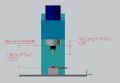
Tool Change Routine
(T14 - call 2.5" Face mill)
(M6 - Perform tool change)
(G0 - rapid feedrate)
(G55-G59 - Choose Work Offset)
(X, Y - Command a Position to move to)
(S - choose spindle speed)
(M03 - Turn spindle on Clockwise, M04 - Counter-clock wise)
T14 M6
G0 G54 G90 X{X} Y{Y} S{SPEED} M03;
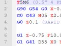
Apply Tool length offset at retract height, Turn on Coolant
(G43 H14 Z2.0 - All codes must be in the same line Apply cutter length offset from record #14 to cuttent tool, move to 2.0 above work at the same time )
(M8 - Turn on Coolant)
G0 G43 H14 Z2.0 M8
Rapid tool to plunge height
G0 Z{Z_PLUNGE}
Plunge to cutting depth at plunge feedrate
G01 Z{Z_DEPTH} F{F_PLUNGE}
Make a straight cut in xy direction at cutting feedrate
G1 X{X_POS} Y{Y_POS} F{F_FEED}
Retract to plunge height at either rapid or retract feedrate
G1 Z{Z_PLUNGE}
Retract to rapid height, turn off colant
(M09 - Turn OFF coolant)
G0 Z{Z_RETRACT} M09
Retract to tool change height, turn off spindle
(G28 G91 Z0 - all coes must be in the same line, move Z axis to HOME POSITION through a reference point)
(G91 Z0 - Causes reference point to be the current location, thus sending axis straight up )
(M05 - Turn off spindle)
G0 G28 G91 Z0 M05
Perform Next tool change or end program
M30(end program)
 G-CODE DARK