Subscribe to Blog
Email Address
 
Search for gcode returned 6 results.
Pages:(1) [1]

HSMAdvisor v2.7.2

September 17, 2023, 4:49 pm by Eldar Gerfanov (Admin)

Good news, everybody!

HSMAdvisor now has a G and M-Code reference page:

Also in this update, I have fixed error messages that appeared after the clean install.
These weren't critical as they appeared only once, but I assume they caused a few new users not to continue using the app, which is quite unfortunate.

The latest update can be downloaded from here: https://hsmadvisor.com/download

Thanks to everybody who sends feedback and suggestions!

Updated G and M-Code reference in FSWizard

August 30, 2023, 1:01 am by Eldar Gerfanov (Admin)

The FSWizard app, available on iOS, Android, and web browsers, recently received a substantial update for its G and M code reference page.

This update includes the addition and updating of the most commonly used Fanuc G and M codes.

Notably, the G code within the sample snippets is now highlighted, enhancing readability.

You can download the update from: https://fswizard.com/

or access it through your web browser: https://app.fswizard.com/#/GCodes.

Thank you to everyone who keeps sending suggestions and feedback!

Cheers!

Notepad++: Absolutely Free G-Code Editor With Code Highlighting

March 20, 2016, 3:28 pm by Eldar Gerfanov (Admin)
NPPGcodeLang3.png

Quite often I see people asking which text editors others use to work with their G-Code.

Some even suggest paid ones.

I am using a free general-purpose advanced text editor called Notepad++.

It is so flexible, it can recognize the language you are working with and turn on the language-specific highlighting for even the G-Code.

I created my own Language profile for it. It is attached to this article so that everyone can download it.

Below is how you can apply this language profile to turn on g-code highlighting:

  1. Download and Install Notepad++ from here: https://notepad-plus-plus.org/download/
  2. Download the custom language file attached to this article to your computer: download file
  3. Launch Notepad++ and go to Language>Define Your Language...
  4. Click on "Import" button and select the G-Code_N.XML Language file you have just downloaded from my site.
  5. After it notifies you that Import was successful, close the "Define" window and restart Notepad++

That is it.

Now when you load any G-Code file with Notepad++, select G-CODE_N item from the "Language" menu and enjoy the full power of the best text editor with g-code highlighting:

A thing of beauty!

Happy Coding!

Update: A friend named Lucas sent me a version of the GCode language definition for Dark Theme. Please see it below in the downloads section. Thanks, Lucas!

G-CODE_N Language G-CODE_N.xml G-CODE DARK G-CODE_DARK.xml Size:0.01 MB
Tool_Length_Offset.PNG

Did you know there are three ways you can touch off your tools?

Because of how Machine Offsets add up, there are several ways CNC machinists can set their Tool and Work Offsets.

This is especially true for Tool Length Offsets.

Tool Offsets can be either Positive or Negative.
Depending on your Machine Shop equipment you should use one or the other.

Regardless of how you set your tool length offset, you apply it the same way.
Right after the tool change and after turning on your spindle and moving to your X Y position above the part.
The very first absolute Z movement should be the line where you apply the tool length offset.

Code
T15 M6; (TOOL CHANGE)
G0 G54 G90 X1.0 Y1.5 S1500 M3;(APPLY WORK OFFSET, MOVE TO THE FIRST POSITION, TURN ON THE SPINDLE)
G43 Z2.0 H15; (APPLY TOOL LENGTH OFFSET WHILE MOVING TO 2.0" ABOVE THE PART)
G0 Z0.1 M08;(MOVE TO FEED HEIGHT AND CARRY ON WITH THE PROGRAM..)

Positive Tool Offsets (gage line tool length offsets)

In the case of Positive Tool Offsets, the offset represents the Length of the tool measured as a distance from the Gauge Line of the spindle (typically spindle nose) to the tip of the tool. The longer the tool, the larger your Tool Length offset will be.

In such a case, Part Z Work Offset will represent the distance between the same Gage Line to the top of the part.

Pro's of Gage Line (Positive) offsets:

  1. Tool Length Offset remains the same between many machines.
    You can just pull the tool out of one machine, Put it into the other one, Type in its Tool Offset and off you go. There is no need to touch off the tool again.
  2. Positive offsets are the easiest to wrap your head around.
    Each definition represents exactly what it does.
  3. Positive Tool Offsets can be measured offline on a pre-setter and then tools can be quickly loaded into the machine without the need to tough off each tool on the machine individually.
  4. In addition to offline pre-setters, most tool tough-off probes also operate in the Gage Line system

Cons of Gage Line offsets:

  1. Can be less practical on machines without tool pre-setters
  2. You are forced to operate with large negative Z Work Offset values
  3. If your tool pre-setter goes down (who never had a dead battery?) you will have a hard time trying to touch off your tools the alternative way.

In summary. Positive or Gage Line Tool Offsets are practical on modestly to highly standardized/automated machining environment.

Negative Tool Offsets

Negative Tool Offsets are dead-simple.
In its easiest form, it represents the (negative) distance between the tip of the tool to the top of the part.
In such case Z Work Offset will equal zero:

This Tool Offset setting style is often used on older machinery in non-automated or non-standardized machining environments.

The initial Top Of Part flat surface is often faced and filler gage is used to set the tool of the top of it.

Pros of Top of Part Negative Tool Offsets:

  1. Dead-simple. Tool Offset represents the distance between the top of the part and the tip of the tool.
  2. This Tool Offset setting style is supported by default on most machines. Just jog the tool to the Top of Part and press "Write Offset"

Con's of this Offset Type:

  1. Tools need to be re-touched for each and every job whenever the height of the part changes
  2. Tool offsets are not interchangeable between several machines
  3. The part needs to be faced in order to set the tool offsets
  4. Can not set tool offsets off a curved or irregular surface: Imagine you need to rework an already machined part. How will you set the tool heights?

Top of Gage Block Negative Tool Offsets:

You can, however, have a little bit of both worlds.

If your machine is not equipped with an automatic tool pre-setter you have to use your machine's manual tool offsetting routine.
You can Touch Off all your tools of a pre-defined gage block off the top of your table or ground vice surface.

In this case, Z Work Offset will equal the distance between the top of the touch-off gauge and the top of your part.

It is extremely handy to touch off your tools of the solid vice jaw using a 1x2x3 block or a special analog Tool Probe with a dial scale.
Just make sure to use the same height (for example the 2-inch side) all the time.

Because when machining in a vise the part stick-out is the most important value, it is easy to calculate the proper Z Work Offset height.
All you have to do is set your Z Work Offset to -2.0 (in the case when you tough your tools 2" above the top of the jaw) and then add the height of your part above the vice.

Pros of Top of Gage Block Negative Tool Offsets:

  1. The same tools can be used without the need to re-set their Tool Offsets between jobs. Only your Z Work Offset changes.
  2. This Tool Offsetting Routine is supported by most CNC machines.
  3. No need to face the top of your part to set your tools or work offset. Just calculate the distance between the top of the gauge and the top of your part.
    A dial indicator can be used to set the Z Work Offset
  4. A tool pre-setter can be used to set the tool offsets. You would need to supply the Machine Gage Height value to the pre-setter software to calculate the proper Tool Offset value.

 Con's of Top of Gage Block Negative Tool Offsets:

  1. The math involved can be a bit challenging at first. Thus not many beginning machinists use it.
    Eventually, however, most figure out and "invent" this method for themselves
  2. Tool Offsets will be different between different machines. So they need to be touched off again when used on a different machine.

Which Tool Offset Setting Type to Use in Your Shop?

It depends on your equipment and shop practices.
You should, however, stick to one particular Tool Setting style and use it across the shop to avoid machine crashes and mishaps.

Before we run any G-Code program, we need to tell the machine where our part zero is.
A Part Zero is simply a bunch of numbers that offset the axis to give the machine a new coordinate point to work from.

Work Offsets is one of the most basic pieces of knowledge any machinist must-have.

Let us account for all the basic coordinate systems and definitions, available in a generic CNC machine

  • Machine Home and (Absolute) Machine Coordinates
  • Work Offset Coordinates
  • Tool Length Offsets

Machine Home and Machine Coordinates: G53

Machine Coordinates (or Absolute Coordinates) is the absolute and constant representation of the machine axis position.
These coordinates never change between Machine Restarts and must remain such. In fact, there is often no way for an operator to adjust the Absolute Machine Axis Home position.

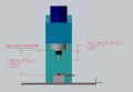
Machine Home is simply that magical place where all Machine Coordinates should become Zero.

To Home the Machine is to start a machine operation, that will move all Axis to their soft limit position where X, Y, and Z-axis reading will be set to zero.

Homing must be done every time you restart your machine. Without it machine does not know where is the position of its table or spindle.

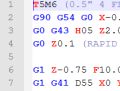
When homed your machine coordinates will read X=0 Y=0 and Z=0 and it is going to look like this:


The point where Machine X and Y intersect is called Table Home Position and the one where the Machine Z-axis starts from is called Spindle Home.

Now, there is no agreement between machine tool manufacturers on where the machine home should be.

Many manufacturers put home in the position where is shown on the picture - this way all our Machine Coordinates will be negative.

Others put Table Home to the lower-left corner and then X and Y Machine coordinates will be positive.

There are a few weird ones, who will put their machine's home position on other (Top Let or Bottom Right) corners and then one of the Axis will be positive while the other one-negative.

But in the end, it does not really matter. As nobody uses Machine Coordinates to machine their parts. All it does however is confuse operators and sometimes make them do silly mistakes.

It does not mean, however, that Machine Coordinates are useless for the operator. They are often used to position the table at the end of the operation for easy loading/unloading or whenever a table needs to move to a safe place for extra-long tool change: any place where the absolute nature of Machine Coordinates is a benefit.

Absolute Movement can be programmed with the G53 code. It is often NON-modal and requires either G01 or G00 motion mode enabled and at least one of the X, Y, or Z coordinates.

Typical example:

Code
...

(move table close to the operator)

G00 G53 X-20.0 Y0

M30

This brings us to the...

Work Offset G54 - G59

Also called Part Zero.
As mentioned before, Work Offsets allow us to specify new coordinate systems based on the relative distance of our Part Zero from the Home Position:

In this picture, the G54 offset will be X=-20.000 and Y-11.000

Each Work Offset is stored in Machine Work Offset Table. This way our program does not need to specify where the part is in relation to the Machine Home.
Your typical Work Offset Table will look like this:

Machine Work Offset Table
G54 G55 etc. G59
X -20.000 X -11.000 X 0.000
Y -11.000 Y -5.000 Y 0.000
Z -13.178 Z -11.000 Z 0.000

Work Offsets are activated using G-Codes G54 through G59
A proper Work Offset should be commanded before any absolute move is made.

Typically Work Offset is commanded right after a tool change is made:

Code
...
T15 M6
G54 G0 G90 X0 Y0 S1500 M3
.....

Work Offset commands are modal and they persist until another work offset command cancels it, the machine gets rebooted, or it gets overridden by a work offset modifier.

X and Y axis Offsets signify the distance from the Machine Home to the Part Zero and Z-Offset value signifies the distance from the Part Zero to the spindle nose in Z Direction.

Looking at the table above it is obvious that something does not quite match the picture: Indeed we have a tool in the spindle.
And because different tools tend to have different Lengths, the distance the Spindle has to travel from its Home to the Top of the part will vary as well!

Thus, to account for different Tool Lengths another offset table was introduced.

Tool Length Offset: H1-H99

Tool length offsets allow machine control to account for the fact that different tools have different Tool Lengths.
Application of Tool Length Offset ensures that Programmed Depth of the cut matches the actual depth of machine movement into the workpiece (or above it).

In other words: Both the T01 which is 3.0 inches long and the T02 which is 5.0" long will move to exactly 0.2" above the part when commanded G00 Z0.2

Machine Tool Length Offset Table
H Offset
1 5.132
2 6.00
3... 8.120
...99 3.000

When the Tool Length Offset is applied, the machine adds the Tool Height to the Work Z-Axis Offset. In such a case Tool Offset means the distance from the Spindle Nose to the tip of the cutter:

(Please note that the setup method is shown above, while easy to comprehend and wrap one's mind around, is not the most practical in terms of manual setup and is mostly used on machines, equipped with an ON-Line or OFF-Line tool pre-setter and/or work probe.
Please see the next article where we explore and compare the two different tool set-up methods.)

Tool length offset is activated with a G43 code, followed by the letter H and then by the address of the length offset in the Machine Tool Length Offset Table.
Typically during programming, in order to prevent crashes and mishaps, Tool Length Offset always matches the Tool Number. But nothing stops you from not following this rule when the situation calls for that.

Tool Length offset must be applied of the very first absolute Z-Axis Move after the tool change:

Code
...
T15 M6 (tool change)
G54 G0 G90 X0 Y0 S1500 M3 (Apply work offset, Turn on the Spindle)

G43 H15 Z2.0 (Apply Tool Length Offset while Moving to the Clearance Height)

...(Start Machining)


This is a very quick overview of the basic Work and Tool offsets available for a CNC Milling Machine.

In later articles, I will explore alternative methods of offsetting Tool and Work Offsets, Work offset modifiers, and extended work offsets available on most machines.

Lessson 3: CNC Canned Cycles, Drilling, Tapping, Reaming and Boring Cycles

September 20, 2015, 2:49 pm by Eldar Gerfanov (Admin)

Canned cycles are used every time we need to drill, ream or tap holes on our CNC machine

Standard Fanuc G-Code language supports more than a dozen canned cycles.

The most common cycles that will cover 99.9% of your g-Code CNC programming work are:

G-Code Name Motion Style
G81 Standard Drilling Feed-In, Rapid-Out
G83 Deep Hole Peck Drilling Incremental Feed-In by Peck Distance, Rapid Out, Repeat
G84 Right Hand Tapping Feed-In,Reverse Spindle, Feed-Out
G85 Reaming/Boring Feed-In, Feed Out

Subsequent holes

You can drill additional holes After your canned cycle has been initiated.
Any line with X Y position will be treated as another hole position.

Each position can have its own Retract value, feed rate and retract height modifier.

G80 - Canned Cycle Cancel Code

After all the holes of the canned cycle have been drilled, it is required to call G80 code in order to cancel the current cycle.

The less common canned cycles are:

G-Code Cycle Name Motion Style
G73 High Speed Chip-Break Drilling Incremental Feed-In by Peck Distance, Stop Feed, Repeat
G74 Left Hand Tapping Feed-In,Reverse Spindle, Feed-Out
G76 Boring, Orient Feed-in, Orient Spindle, Rapid-Out
G82 Spot Drilling Feed-In, Dwell, Rapid-Out
G86 Boring Feed-In, Spindle Stop, Rapid-Out
G87 Back Boring Cycle Orient Spindle, Move to Insert Point, Turn Spindle On,
Feed-In to target Z, Retract to start Z, Move to insert point, Rapid Out
G88 Manual Dwell Boring Cycle

Feed-in, Dwell, Stop Spindle,
Stop Program to let the operator manually retract the tool

G89 Dwell Boring Cycle Feed-In, Dwell, Feed-Out

Support of each of these cycles depends on your particular machine. So make sure to double-check you manual before using any. Especially the ones from the second table!

Retract control codes:

G98 and G99 codes control Z- retract distance between holes in the same cycle.
These codes must be applied on the same line as or before the canned Cycle. Or BEFORE each hole in the cycle

G-Code Code Name Motion Style
G98 Clearance Height Retract After each hole Tool retracts to the last rapid - Z height before the application of the canned cycle. Used when there is need to avoid clamps or part features that are above the R-value height.
G99 R - Height retract After each hole Tool retracts to the R value height of the canned cycle

This is how G98 retract modifier behaves:

And this is how behaves the G99 retract modifier:

Where part geometry is calling for use of G98 you can combine G98 and G99 to save on some rapid time:

As you can see we need to apply G98 on the hole after which we need to retract to the clearance height.

The codes shown on this picture are missing X,Y locations in some places. The correct program would look like this:

Code

G0 Z0.5
G81 G99 X1.5 Y2.0 Z-1.0 R0.1 (Drill First Hole. G99 - Retract to R-height)X2.0 Y2.0 R-0.75 (Drill Second Hole)
G98 X2.5 Y2.0 R-0.75(Drill Third Hole, After it Retract to 0.5" Z-Clearance height)
G99 X3.0 Y2.0 R.1 (Drill fourth hole. Retract to R-height)
X3.5 Y2.0 R-0.7 (Drill fifth hole. Retract to R-Height)

G80 (Cancel Canned cycle)

G0 Z0.5 (retract to clearance height)

The anatomy of a standard drilling program is as follows:

Code

O0001 (COMMENT OR PROGRAM NAME)

(Starting safety blocks)
G20 G17 G40 G49 G80 G90

(Tool Change Routine)
T15 M6

(Position Axis over the work)
G0 G54 G90 X1.5 Y2.125 S1500 M03;

(Apply Tool length offset at retract height, Turn on Coolant)
G0 G43 H15 Z2.0 M8

(Rapid tool to Safe Clearance height)
G0 Z1.0

(Activate Canned Cycle and drill the fist hole)
G81 G99 X1.5 Y2.125 Z-0.5 R0.1 F12.0

(drill subsequent holes)
X1.75 Y2.5
G98 X2.5 Y3.0 (Retract to Clearance height to avoid clamp after THIS hole)
G99 X3.5 Y3.0 (Switch back to retracting to R-value)

(Cancel Canned Cycle)
G80

(Retract to Clearance height, turn coolant off)
G0 Z2.0 M09

(Turn Spindle Off, Retract to TC height)
G0 G91 G28 Z0 M05

(End Program)
M30


Canned Cycles Format

G-Code Name Format Standard Example
G81 Standard Drilling

G81 X Y Z R F [K or L]

  • X , Y - Location of the first hole
  • Z - Absolute or relative depth of the hole (depending on your control)
  • R - Retract Height
  • F - Feed Rate
  • [K or L] - Number Repeats

G81 X1.5 Y1.0 Z-0.5 R0.1 F15.0
X2.0 Y1.5 (subsequent hole 1)
X2.5 Y2.1 (subsequent hole 2)
G80

G83 Deep Hole Peck Drilling

G83 X Y Z R Q F [K or L]

  • X , Y - Location of the first hole
  • Z - Absolute or relative depth of the hole (depending on your control)
  • R - Retract Height
  • Q - Peck Depth
  • F - Feed Rate
  • [K or L] - Number Repeats
G83 X1.5 Y1.0 Z-0.5 R0.1 Q0.25 F15.0
X2.0 Y1.5 (subsequent hole 1)
X2.5 Y2.1 (subsequent hole 2)
G80
G84 Right Hand Tapping

G84 X Y Z R F [K or L]

  • X , Y - Location of the first hole
  • Z - Absolute or relative depth of the hole (depending on your control)
  • R - Retract Height
  • F - Feed Rate (Usually in Inches per Revolution,depending on your control)
  • [K or L] - Number Repeats
G84 X1.5 Y1.0 Z-0.5 R0.1 F0.049
X2.0 Y1.5 (subsequent hole 1)
X2.5 Y2.1 (subsequent hole 2)
G80
G85 Reaming/Boring

G85 X Y Z R F [K or L]

  • X , Y - Location of the first hole
  • Z - Absolute or relative depth of the hole (depending on your control)
  • R - Retract Height
  • F - Feed Rate
  • [K or L] - Number Repeats
G85 X1.5 Y1.0 Z-0.5 R0.1 F15.0
X2.0 Y1.5 (subsequent hole 1)
X2.5 Y2.1 (subsequent hole 2)
G80

As already noted above each control will handle these cycles a little differently.
So be careful!

Pages:(1) [1]
Sing In

© 2009-2022 Eldar Gerfanov. All Rights Reserved.
© 2009 Eldar Gerfanov. Materials on this site are presented as is and are mostly for educational use.

You may freely reproduce information presented herein without any consent from me, provided you include link to this site.
In case when i am not the copyright holder, you may want to contact proper owner of material. Anyway, they are freely available on the Internet.
If you hold the copyright right for any of the materials on this site and want them removed, please contact me here